¶ Overview
With the frame built, we are now ready to start putting together the components to enable movement of the various components of the X301.
¶ Hardware
¶ Purchased Parts
A member of our community is working through this build and updating the wiki. This is a running tali of parts that will be used to get to where he currently is. Currently, he is just about to start building the bed.
- (2) Flexible Shaft Coupling
- (2) Stainless Steel Lead Screw (400mm, T8 OD, 8mm pitch, 2mm lead /w nut)
- (5) MGN12H 400mm Linear Rail, Single Block
- (4) Nema 17 High Torque stepper motors
- (8) 8mm M5 screws *
- (8) M5 t-nuts
- (52) 8mm M3 screws *
- (16) M3 t-nuts
- (8) M3 washers
* For the most part, the style (pan/socket head) screw here is a matter of personal preference. It seems logical to make sure they are all the same for the sake of appearance.
¶ Old List
The following parts list is old and is being left only while the above parts list is being updated.
- X301 Motion Kit
- (4) Flexible Shaft Coupling
- (2) Stainless Steel Lead Screw 400mm T8 OD 8mm pitch 2mm lead w/ nut
- (5) MGN12H Linear Rail 400mm long, Single Block
- (4) Nema 17 1.8 deg high torque stepper motors
- (1) GT2-6mm Belt (5 Meters minimum)
- (6) GT2 Idler Pulley 20 Teeth 5mm bore 6mm Width
- (2) GT2 Idler Pulley Toothless 5mm bore 6mm Width
- (2) GT2 Pulley 20 Teeth 5mm Bore 6mm Width (X/Y Stepper Motors)
- (2) M5 35mm Socket Head Screws
- (2) M5 Washers
- (4) M5 40mm Socket Head Screws
- (6) M5 12mm Socket Head Screws
- (12) M5 8mm Socket Head Screws
- (42) M3 8mm Socket Head Screws
- (1) M3 8mm Button Head Screw
- (8) M3 12mm Socket Head Screws
- (8) M3 Washer
- (22) M5 Nuts
- (2) M4 20mm Socket Head Screws
- (1) Pancake Stepper Motor
¶ Printed Parts
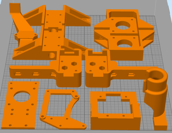
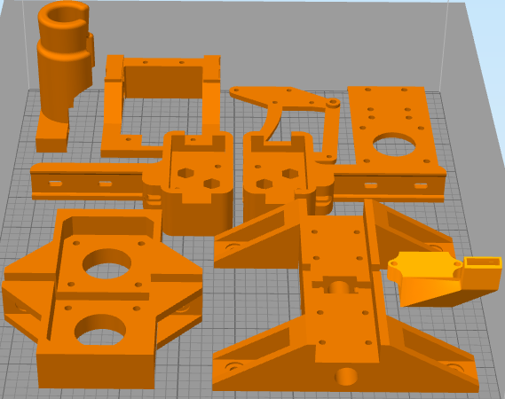
- (2) Z Carriage Brackets
- (2) Z Axis Motor Mounts
- (1) XY Bracket Bottom V2 Right (or Deprecated Version used in Video)
- (1) XY Bracket Bottom V2 Left (or Deprecated Version used in Video)


¶ Old List
These parts were originally listed here, but were not used. Keeping them here so I don't forget about them elsewhere.
- (1) Filament Feed Mount
- (1) Cable Plate Mount (or PCB Version)
- (1) Carriage - Front Plate
- (1) Carriage Belt Body (or Slim Version)
- (1) Cooling Fan Mount Plate
- (1) Part Cooling Duct (or Non-Volcano Version)
¶ Mods to Consider
- 3-Z Screw Converion - Additional Hardware Required. This mod by johanmalay increases the number of Z-Axis stepper motors from 2 to 3 to further improve auto bed leveling.
- Composite XY Brackets - Additional Hardware Required. Replaces XY Bracket Bottoms (and parts used in later steps) with ones that print together in one piece. Adds rigidity, removes pressure from screws allowing them to be tightened to the correct pressure.
- Pillow Blocks - Additional Hardware Required. This mod relives downward stress on the z-axis stepper motors. This mod is highly recommended as it is inexpensive and should increase the lifespan of your z-axis stepper motors.
- Braced XY Motor Brackets - Adds a bit more material to reduce the flex when printing quickly
¶ Video
DIY CoreXY 3D Printer | LayerFused X301 Part 2 - Motion Control
¶ Instructions
¶ Linear Rail Installation
Note that we will be using several 8mm M3 screws to attach 3D Printed parts to linear rails. Ensure you do not overtighten the screws or you may damage the 3D Printed parts and/or the linear rails.
¶ X/Y Linear Rails
The X and Y linear rail installation is pretty straight forward. Make sure that you have some sort of retaining clip on the Linear rail to prevent the carriage from falling off the end of the rail. Some linear rails may come with some in place from the factory.
Add a minimum of (4) equally spaced M3 screws and t-nuts to (4) of the 400mm linear rails. You can use more if you would like, but (4) seems sufficient.
[Insert picture of rails w/ screws and nuts]
Place (1) linear rail on the right top 2020 extrusions, then repeat for the left side. Before tightening down the screws make sure that the rail is pushed all the way back to the printed part. It would also be a good idea to make sure that the rail is aligned in the center of the extrusion. Tighten down all the screws and ensure that the carriage slides smoothly on the rail.
[Insert picture of rails on left/right extrusions]
For the X axis linear rail you will need the 2 Carriage blocks. These blocks have a hole for a nut, that hole should towards the back of the printer. Slide the linear rail into the opening on the carriage block. This will be a tight fit, so you may have to tap it on the table to get it aligned properly. Don't worry about tightening these down as we will be taking it apart to install the idler pulleys later.
[Insert picture of carriage blocks on linear rail]
Once you have the 3D printed parts installed on the linear rail place the place the 3D printed parts over the carriage blocks on the Y rails. The parts should slide over the block snugly. Fasten the 3d printed part with (4) 8mm M3 screws. Do not over tighten becasue you can crack the part or damage the carriage block underneath.
[Insert picture of carriage rail installed]
¶ Z Linear Rails
Attach the linear rails on the 2040 extrusion at the front most slot. This linear rail aligns with the whole length of the 2040, make sure that it is aligned flush with either the top of the extrusion.
[Insert picture of installed Z linear rail]
Next prepare the Z motor mounts. Each mount requires (2) 8mm M5 screws with t-nuts and (4) 8mm M3 screws for the motor. You will want to mount the motor in the 3D printed part with the connection for the motor facing into the enclosure.
[Insert picture of z-motor mounts without motor]
[Insert picture of z-motor mounts with motor]
Install the motors and mount on the second slot from the top of the left and right 2080 extrusions. You want the shaft of the stepper motor to be aligned with the linear rail, but do not worry about making it perfect at this point. Ensure the motor mounts are snug, but don't bother tightening them too much as we will loosen them in order to adjust them in a moment.
[Insert picture of installed motor mounts]
Install the flexible coupler onto each of the stepper motors. Make sure that the coupler is aligned on both sides. Depending on the couplers that you have there will be a stop in the center of the coupler. Align the step with the top of the motor peg. Tighten the coupler but not so tight that it deforms. If your motor peg has a smooth side, tighten a grub screw onto that smooth side first, then tighten the other grub screw.
¶ Motors
¶ Z Carriage
Remove the brass nut from the threaded rod and insert into the 3D Printed Z Carriage Bracket. The fit will intentionally be very snug. Once the brass nut is installed, secure it with (2) 8mm M3 screws. Insert (2) 8mm M5 screws with t-nuts into the sides. These are for the bed assembly that will be installed later.
[Insert picture of z carriage brackets with brass nut and t-nuts]
Secure the carriage mounts to the Z Linear Rail blocks with (4) 8mm M3 screws each. Next you will have to manually thread the lead screw into the block and all the way down to the coupler on the stepper motor. Leave a gap of about 6 inches between the coupler and the brass nut and press the lead screw as far into the coupler as it will go.
[Insert picture of lead screw in coupler]
Ensure the motor mount t-nut screws are loose enough that you can move the motor mount back and forth, then decrease the gap between the coupler and the z carriage bracket to about 1 inch. Adjust the motor mount until the top of the lead screw is properly aligned with the top of the z linear rail, then tighten down the motor mount and flexible coupling grub screws.
[Insert picture of aligned threaded rod and z carriage bracket]
To ensure alignment of the stepper motor and the threaded screw rotate the coupler up and down a bit. It should move smoothly with no binding. If it binds at all you need to adjust the Z Stepper motor until there is no binding and things move smoothly.
If you are following along with the video, it jumps to building the bed at this point in time. We are going to finish the motors, then come back to the bed in the next step.
¶ X/Y Motors
Using (4) 8mm M3 screws and washers each, attach the (2) X/Y Stepper Motors with the wires facing towards the front of the printer. Don't bother tightening them down all the way as we will tighten them after we install the belts.
[Insert picture of the Installed X/Y Motors]
Previous Step Back to Guide Next Step