¶ Overview
The Frame is the most important part of the 3D printer. This needs to be rigid and square. Take your time and ensure that everything is put together properly and as square as possible.
¶ Hardware
¶ Purchased Parts
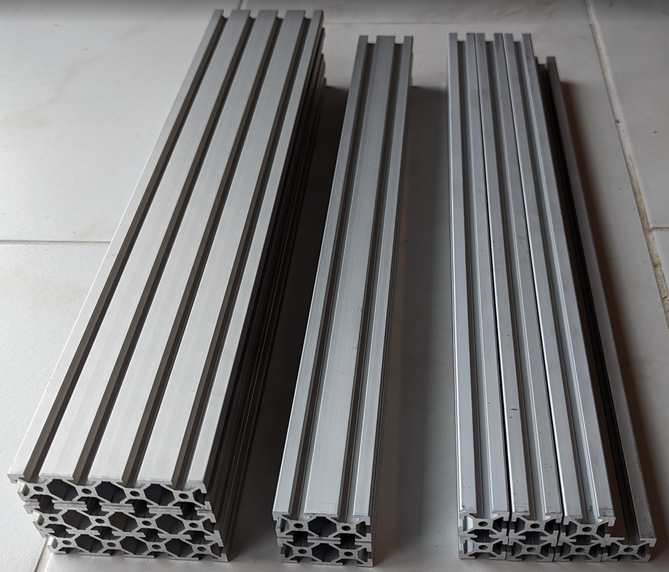
- (3) 400mm 2080 aluminum extrusion
- (2) 400mm 2040 aluminum extrusion
- (7) 400mm 2020 aluminum extrusion
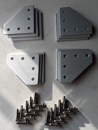
- (12) Aluminum T-slot L-shape joining plate
- (10) Inside corner bracket
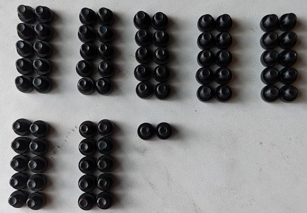
- (88) 8mm M5 screws *
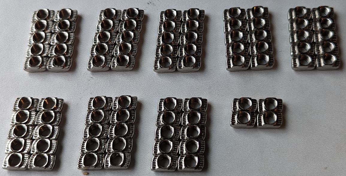
- (88) M5 t-nuts
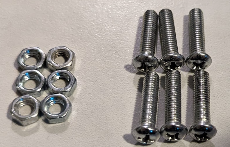
- (6) 12mm M5 screws *
- (6) M5 nuts
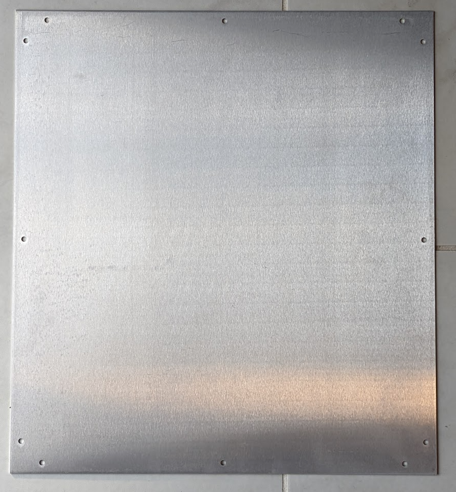
- Aluminum Base Plate
* For the most part, the style (pan/socket head) screw here is a matter of personal preference. It seems logical to make sure they are all the same for the sake of appearance.
Note that the pictures may show a different count than the required number of parts. These pictures were taken before the build was finished and the builder didn't have spares to take count-accurate pictures. The numbers written above are correct.
¶ Printed Parts
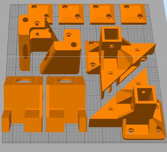
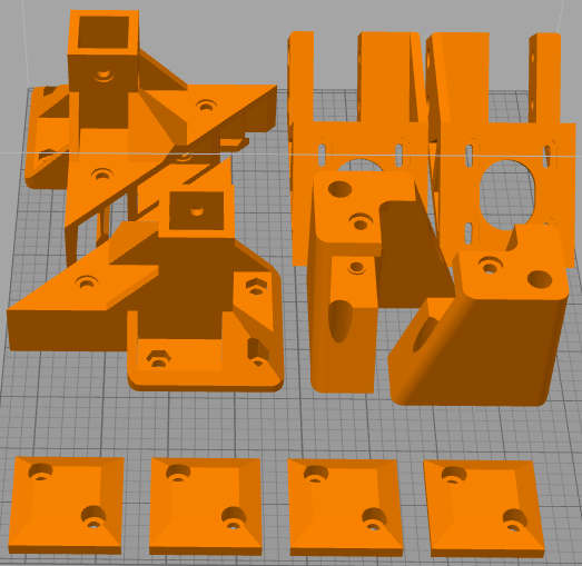
- (2) Rear Corner Bracket Top
- (1) Rear Pully Bracket Left
- (1) Rear Pully Bracket Right
- (1) XY Motor Bracket Left
- (1) XY Motor Bracket Right
- (4) TPU Feet
¶ Video
DIY 3D Printer (CoreXY) | LayerFused X301 Part 1 - Frame
¶ Mods to Consider
- Right Angle Corner Brackets: Possible improvement to the structural rigidity and squareness
¶ Instructions
T-nuts have a small learning curve. If you are unfamiliar with them, it is likely worth your while to grab an L-shape joining plate and (5) M8 8mm screws with (5) M8 t-nuts and practice installing them properly. A good technique is to loosly attach the t-nut(s) to the screw(s) through the joining plate, press the t-nut(s) into the desired extrusion, then go through one at a time and untighten one all the way while maintaining pressure to ensure it does not move, then tigthen it down. Once tight, lightly attempt to remove the part to see whether you were successful. With some practice, you should be able to feel when a t-nut was installed correctly based on the number of times you turned the screw.
This video does a nice job of explaining this trick.
Squaring your 3D Printer is a critical step to take at multiple points during this build. If your printer is not square, you will have problems that will eventually require you to take the entire 3D Printer back apart and start over.
This video does a nice job of explaining squaring a CoreXY 3D Printer. We also have a text-based guide here.
¶ Electronics Box
¶ Ready the Base Plate
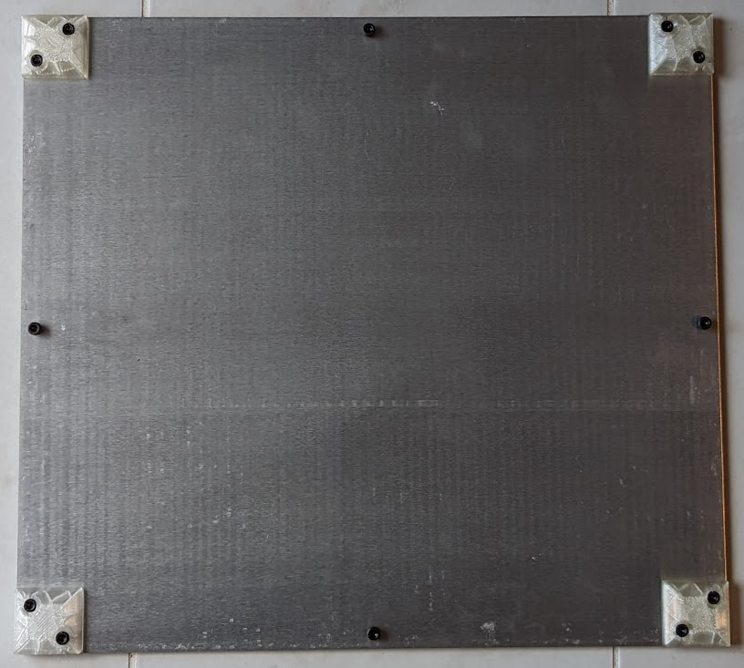
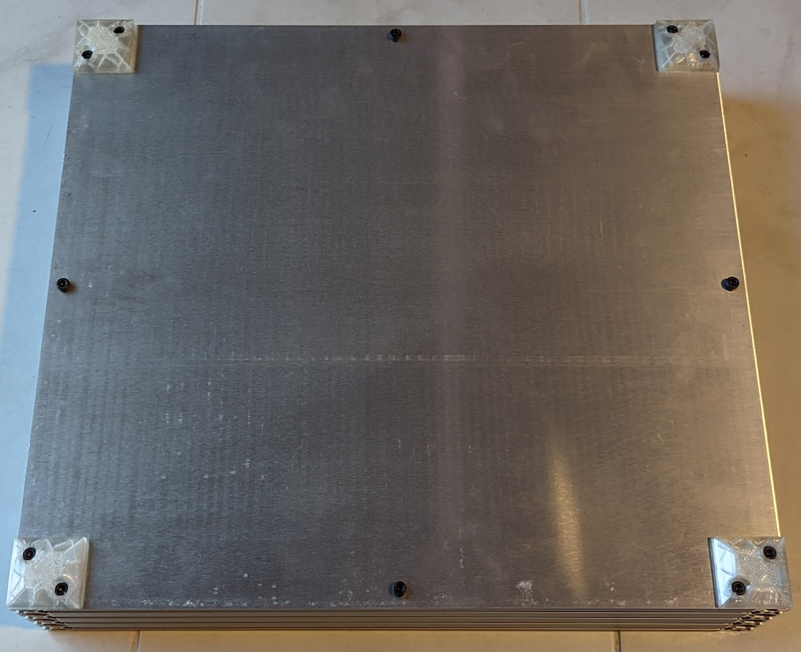
Use the TPU feet as a guide to mark the holes on all 4 corners of the base plate and drill the corresponding 8 holes. Along the side, use the TPU feet as a guide for distance from the edge to match the extrusion and drill 4 more holes. LayerFused Shop Aluminum Base Plate comes pre-drilled, which removes this step.
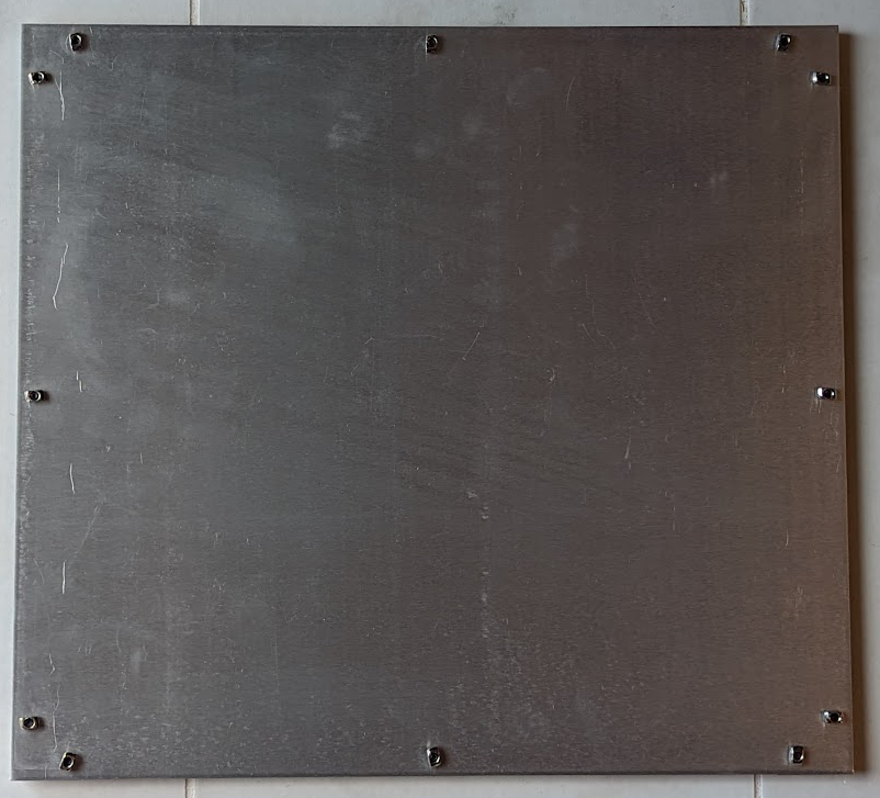
Attach the TPU feet with (8) M5 8mm screws and (8) t-nuts. Also go ahead and insert (4) M5 screws with (4) t-nuts in the center holes on all 4 sides. You can use the same M5 8mm screws that the TPU feet used, though 6mm is all that is needed if you want to use those instead.
¶ Front and Side Extrusions
It is worth your time to confirm that everything is square after each of the following steps.
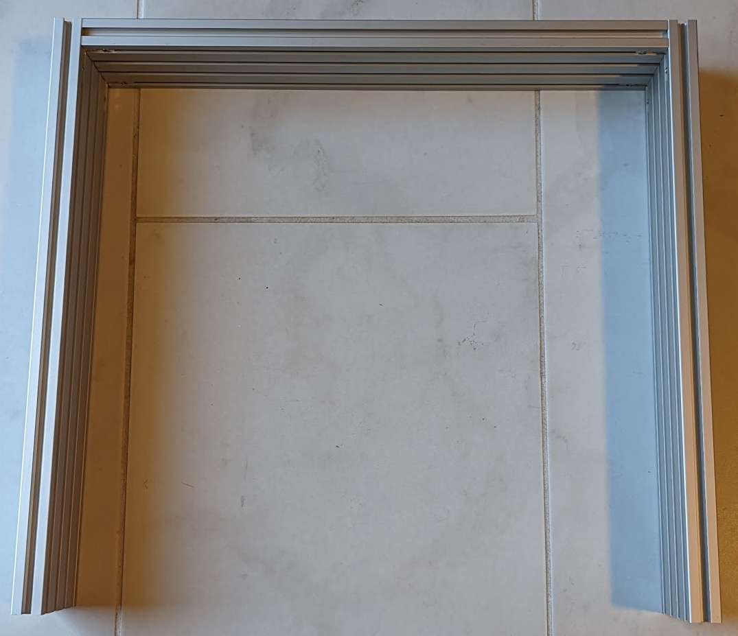
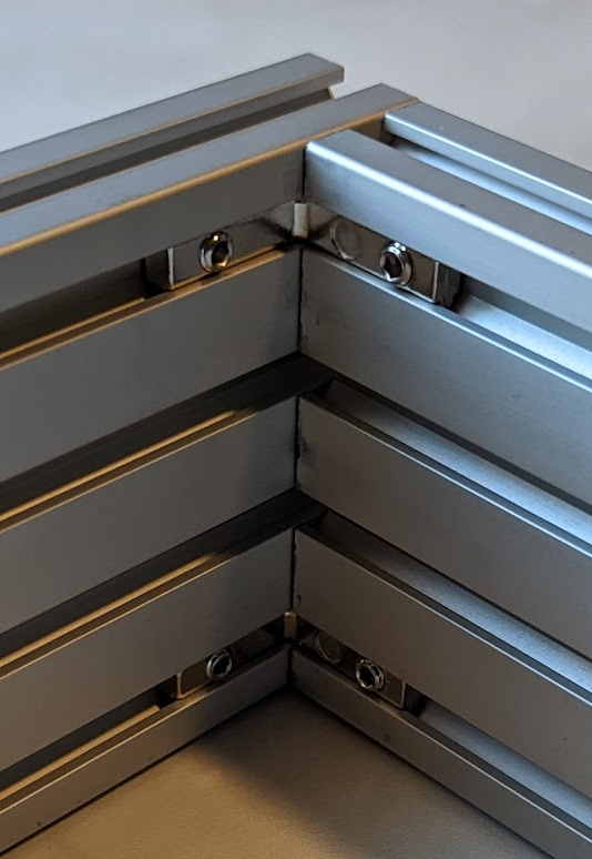
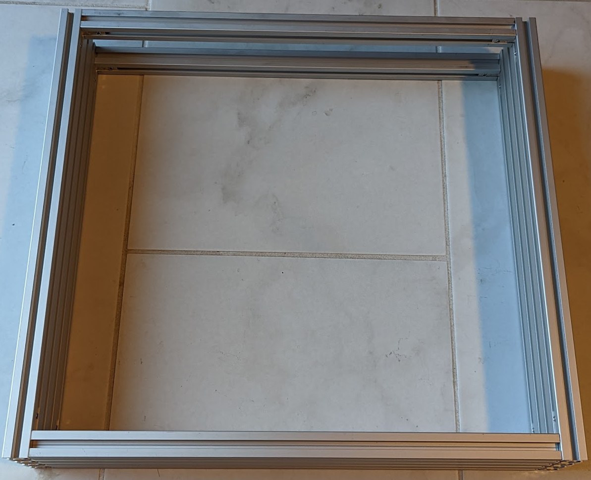
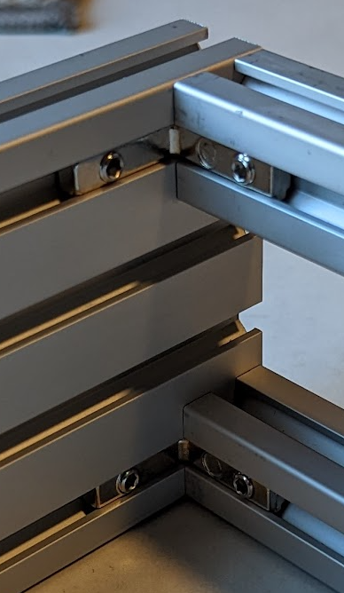
Use the inside corner brackets to connect all (3) 400mm 2080 extrusions together. You only need one inside bracket in the top slot and the bottom slot. You should have (4) inside brackets on one piece of the 400mm 2080. The (2) side 400m 2080 extrusions will connect to the front 400mm 2080 creating sort of a "U".
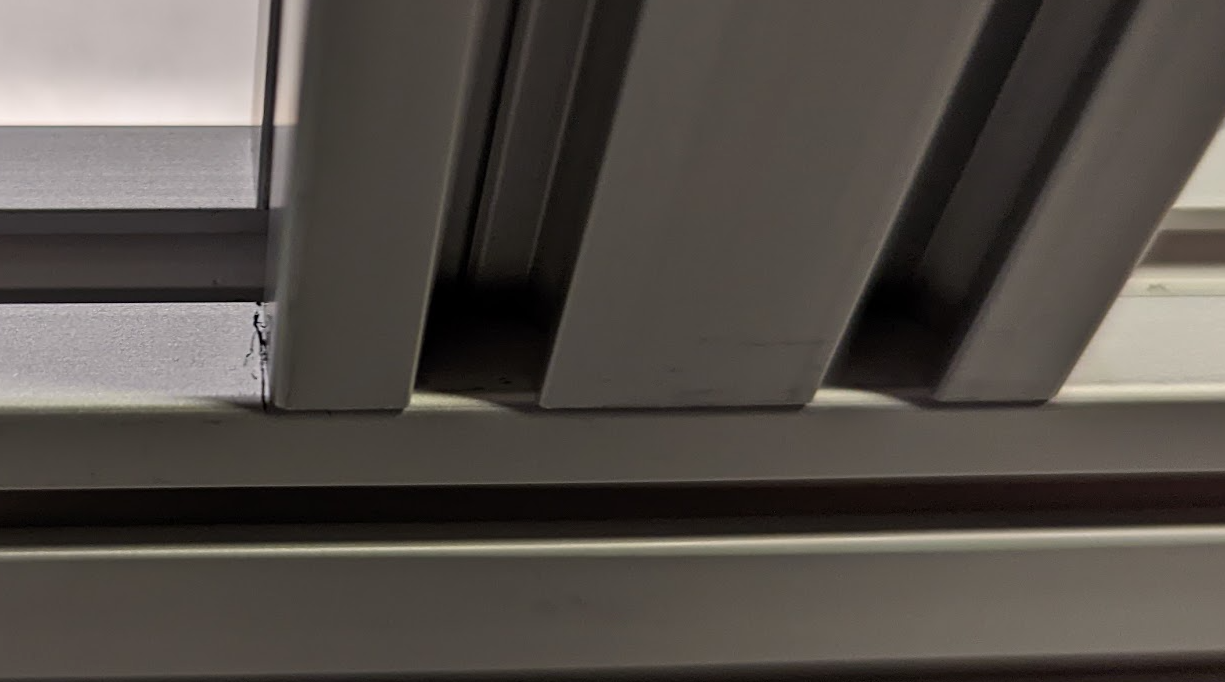
Ensure the front extrusion is sandwich'd between the side extrusions as shown in the following photo. There is a correct and incorrect way to do this and if you do it wrong, you will need to take your printer all the way back apart.
¶ Back Extrusions
Next use (2) of the inside corner brackets to connect (1) 400mm 2020 extrusion to the inside corners on the top most slot of the open end on the 2080 extrusion assembly.
Flip the Electronics Box over so the 400mm 2020 extrusion that you just installed is now on the bottom. Using (2) inside corner brackets install (1) 400mm 2020 extrusion the same way as the previous one. This will create an opening on the bottom rear of the printer to allow for cables to run through.
¶ Attach the Base Plate
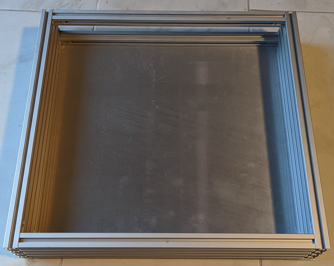
Next turn the electronics box on its side to install the base plate. It is going to take some wiggling to get all of the t-nuts to fall into place. Once you have everything aligned and the baseplate is flush with the extrusion, tighten everything down and flip the enclosure back over. This is the final ideal time to confirm everything is square within the electronics box, so ensure you take the time to do so.
¶ Uprights
¶ Back Upright Extrusions
For the uprights on the printer we are going to use (2) 400mm 2040 extrusions and (2) 400mm 2020 extrusions.
One of the screws on the corner brackets will need to be reversed. Slide (1) inside corner bracket into the top of the side 400mm 2080 and use a 2020 extrusion to align the bracket to make it easier to tighten down. Attach (1) 400mm 2020 extrusion to the frame using the inside corner bracket. Once that is installed, use (2) of the bonding plates to attach the 2020 extrusion to the 2080 extrusion. Note that the bonding plate that attaches to the back of the printer will only use (3) M5 screws and t-nuts. This is because a corner bracket gets in the way of the remaining (2) screws. Repeat the process for the other corner as well.
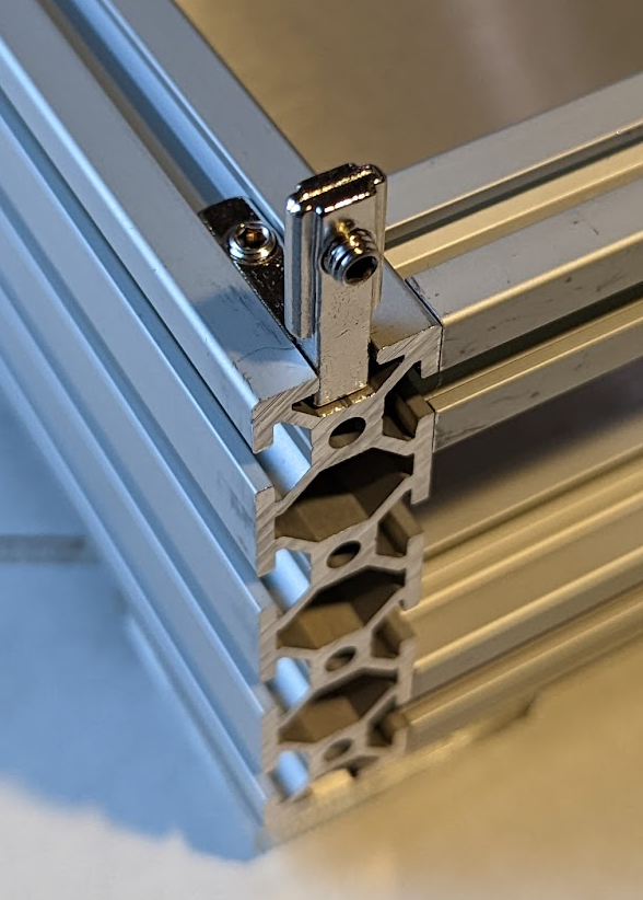
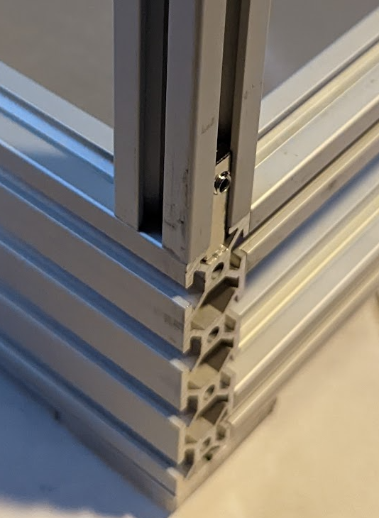
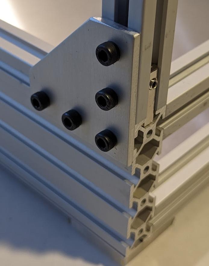
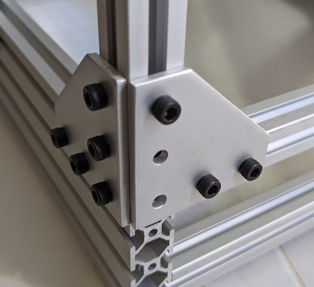
Note that the above picture has a bonding plate not seen in later pictures. The builder missed this plate in the initial build and came back for this picture after the fact.
¶ Z Upright Extrusions
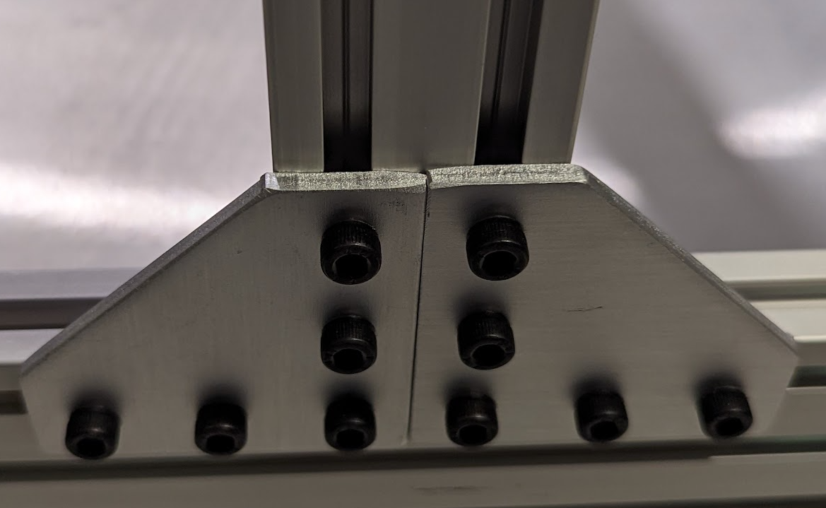
We are going to mount the (2) 400m 2040 uprights 180mm from the rear uprights. Using a ruler measure out 180mm and put a mark on the extrusion. Align the rear of (1) 400mm 2040 extrusion with the mark that you have made on the 400mm 2080. Using (2) bonding plates attach the 400mm 2040 to the base's 2080 extrusion. Repeat this process on the other side.
Make sure that both of these uprights are aligned so there is 180mm between the back extrusion and the z extrusion.

¶ Rear Corner Brackets
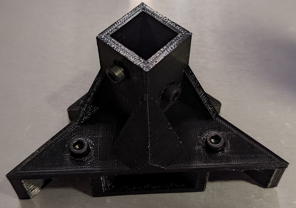
Prepare the (2) 3D printed rear corner brackets by adding (6) M5 screws and t-nuts that will attach to the back 400mm 2020 vertical extrusion. Once the 3D printed part is prepped, slide it over the 2020 extrusion until the inside bottom is flush with the top of the extrusion. Tighten the screws up on the extrusion. Do this for both rear uprights.
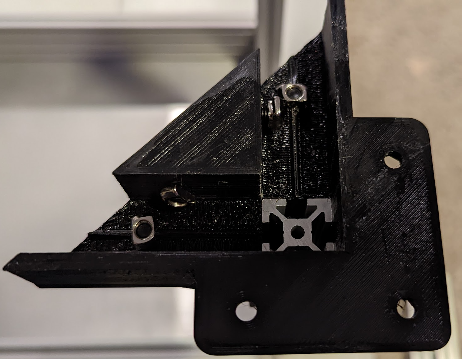

Once you have those installed, connect the rear uprights with (1) 400mm 2020 extrusion. This extrusion will slide into the channels on the 3D printed parts. Tighten down the screws on the this new horizontal extrusion.

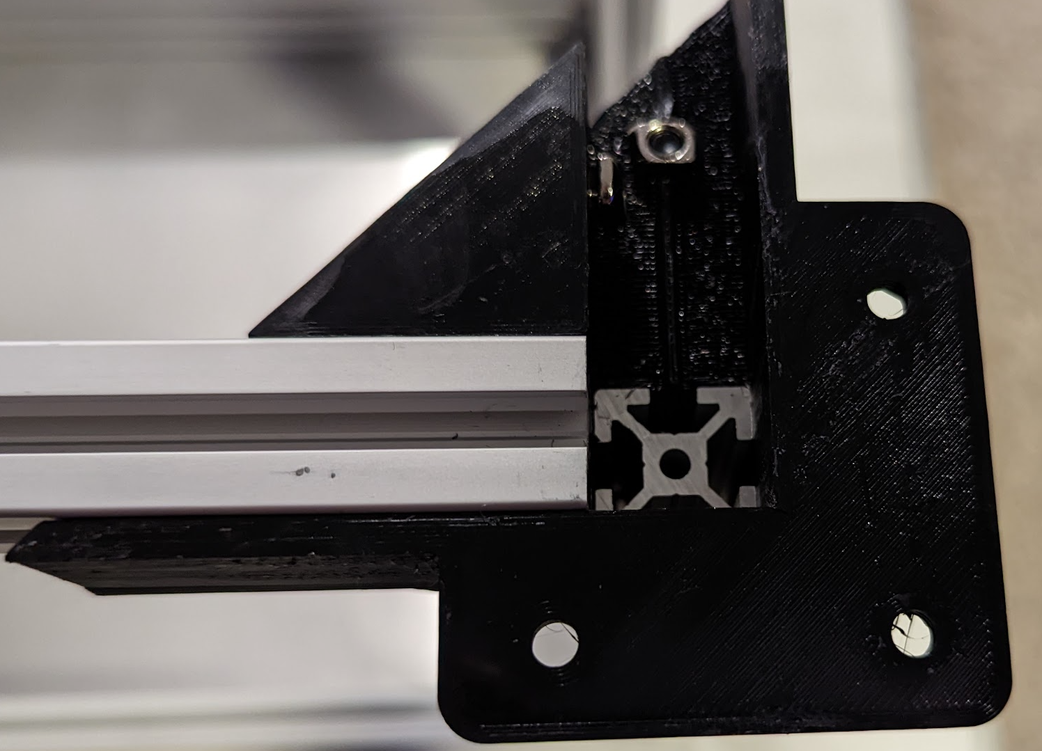
Next, slide (1) 400mm 2020 extrusion into the other channel flush all the way to the back of the 3D printed part. Repeat this for the other side. Do not tighten these yet.
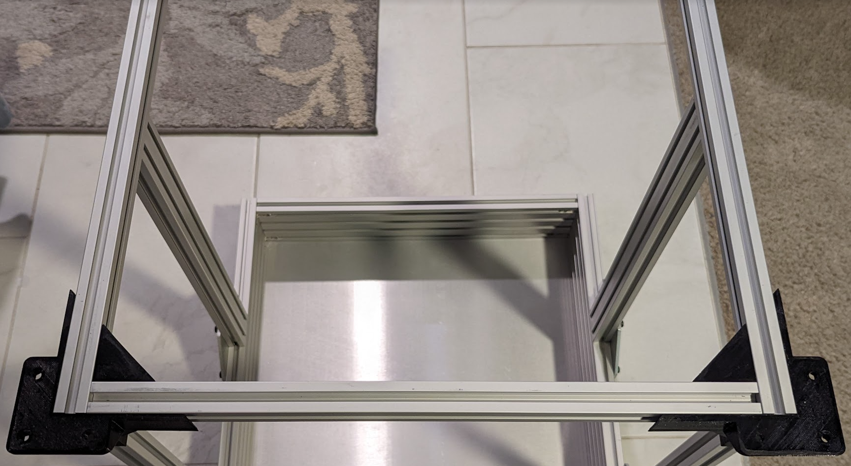
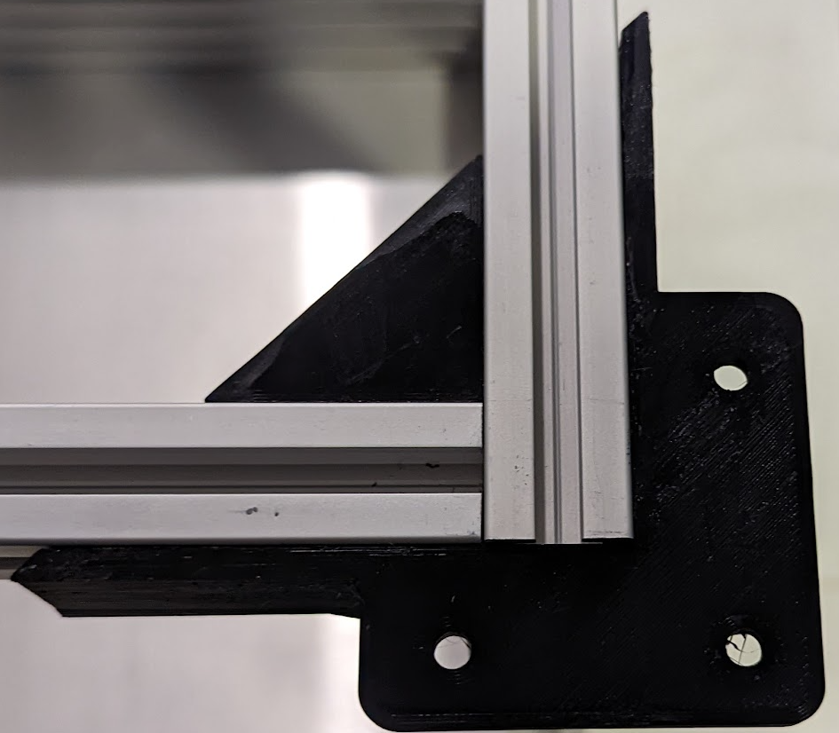
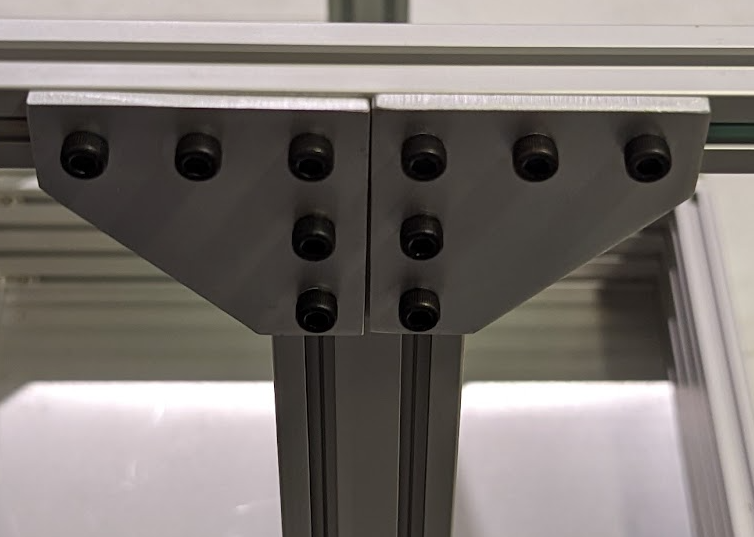
Using (2) bonding plates, attach (1) 400mm 2040 z-extrusion to (1) 400mm 2020 horizontal extrusion. Repeat the same steps for the opposite side.
¶ Rear Pulley Towers and Stepper Mounts
¶ Rear Pulley Towers
For the rear pulley towers you are going to use (3) M5 12mm screws with nuts. You can use longer screws if you find that the 12mm are a little too short. The towers must be oriented so the openings are closest to the front of the picture.
The easiest way to install them is to insert the nut into the bottom first, then hold it in place with your finger as you tighten the screw. Do not overtighten as you could crack the part.
Note that this step requires a fairly thin screwdriver and you may need to find a different one than the one you have been using.

¶ Stepper Mount Attachment
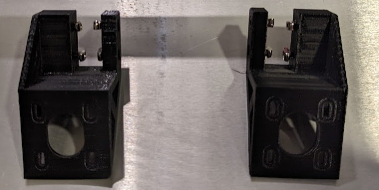
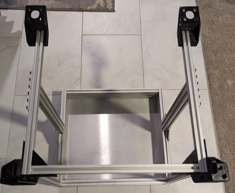
Prepare the 3D printed XY Motor Brackets by installing (4) M5 8mm screws and t-nuts. Once the part is ready simply slide the 3D Printed part with Tnuts over the protruding extrusion on the front of the 3D printer. Ensure that the wider portion of the 3d printed part is on the outside of the frame.
¶ Final Checks
After you have completed all steps, ensure the following:
- All screws are tightened, without overtightening those which go through 3D printed parts.
- The frame is square. Any location that makes a square or rectangle should be confirmed square as explained in our squaring guide.
- Ensure there are no unintended spare parts. The parts list at the top of the page should be accurate. If you cannot determine where your spare parts are coming from, feel free to reach out to the Community and we will get you on the right track.
Previous Step Back to Guide Next Step