¶ LayerFused X301 Part Printing Guide
There have been a number of requests for a guide on how to print the parts for the X301. This post should answer most questions and will be updated as necessary.
¶ CALIBRATION
Before we talk about anything else in this guide make sure your printer is properly calibrated on the X/Y/Z and E axis. Print a calibration cube, make sure it is properly sized in all directions. Run an extruder test and make sure you're extruding the correct amount. Nothing is more frustrating than printing a part only to find out it wont fit over the extrusion or you find that its too loose and introduces play into the printer. Spend the time upfront to calibrate your printer and you'll find everything will go much better. You can use horizontal expansion to adjust for things in your slicer but its much better if your printer is tuned properly before starting this project. If you're not sure how to do this your path to building this printer will likely be very difficult. This is a core competency for 3D Printer use and building. There are dozens of resources available on the internet and YouTube to assist you with this.
¶ FILAMENT CHOICE
You can use your filament of choice for the printer. However there are a few things to consider when choosing filament. You want your printer to be strong & rigid and therefore you want to print using filament that supports that. PLA is an exceptional filament for the printer and has good strength and cost to it. However if you plan to print later in something like ABS which requires a heated enclosure PLA becomes a poor choice. PETG would be a better choice if you plan to print using a heated enclosure. LayerFused is now offering Pro PLA that has the properties of ABS/PETG and ease of printing of PLA. It has been our experience that clear PLA performs much better than PLA with considerable pigment (including black). The more additives to the PLA the parts seem to have more flexing than ones that do not. Translucent or clear PLA seems to work best since its in a near natural state. Largely though it is your choice how you print the parts and what colors you use. No formal tests have been done using a specific filament so while there is no backing data to my claims here it is based on observations printing parts for this printer over the course of a year.
¶ TPU PARTS
There are only 2 parts that are printed in TPU. The printer feet and the heat bed relief. The feet can be printed anywhere from 10%-30% infill and should have at least 3 shells on the outside layer. The lower infill provides more shock absorbing where the higher infill causes the feet to be firm. The heat bed relief should be printed at 100% infill. The 3D Printer feet can be substituted with off-the-shelf furniture feet as well. A number of people have chosen to use that in lieu of buying TPU and printing only 2 parts with it. The heat bed relief is an important part but you may be able to find an off-the-shelf replacement for that as well.
¶ STRUCTURAL PARTS
The 3D Printed parts that comprise the mounts, extrusion junctions, etc should be printed at least at 20% infill with 30% preferred. You should use at least 3 shells with 4 preferred. This provides a very rigid print for these parts. It is important that these parts are as rigid and strong as possible to produce a printer which will last many years without replacing parts. .2 layer height is sufficient for any of the parts on the printer.
¶ FAN DUCT
It is recommended that the Fan Duct be printed at a .1 or .12 layer height. This results in a smoother fan body since air flows through it. The print time difference is marginal but the results are much better.
¶ COSMETIC OR ACCESSORY PARTS
These parts are items like the front display panel, extrusion covers and filament guides. They do not need as much strength and can easily be printed at 10%-20% infill with 2 shells with 3 shells preferred. .2 layer height is sufficient for any of the parts on the printer.
¶ ORIENTATION & SUPPORTS
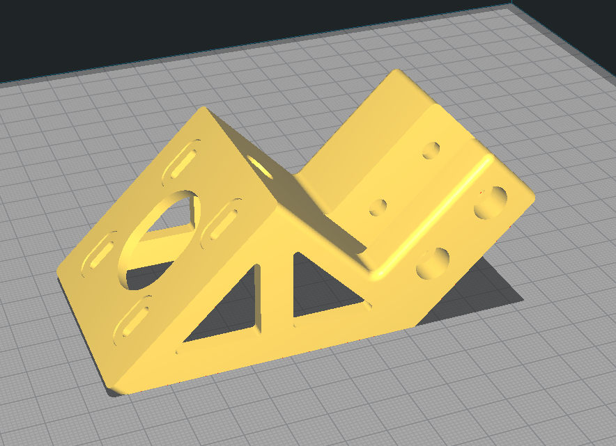
None of the parts require supports. They only require rotation so they will print without them and good part cooling. The one that usually comes up is the stepper mounts. These do in fact print without supports.

Proper Orientation of the Stepper Mounts to print without supports
- Using "Print thin lines" in cura is helpful for getting the base to print correctly.
- Using 5 outer shells is helfpul in print speed as less infill is required and less printer vibration from the small infill on the left and right sides of the bracket mounts.
As you can see in the photo above no supports are necessary to print this. The other one that comes up frequently is the rear top corner brackets.

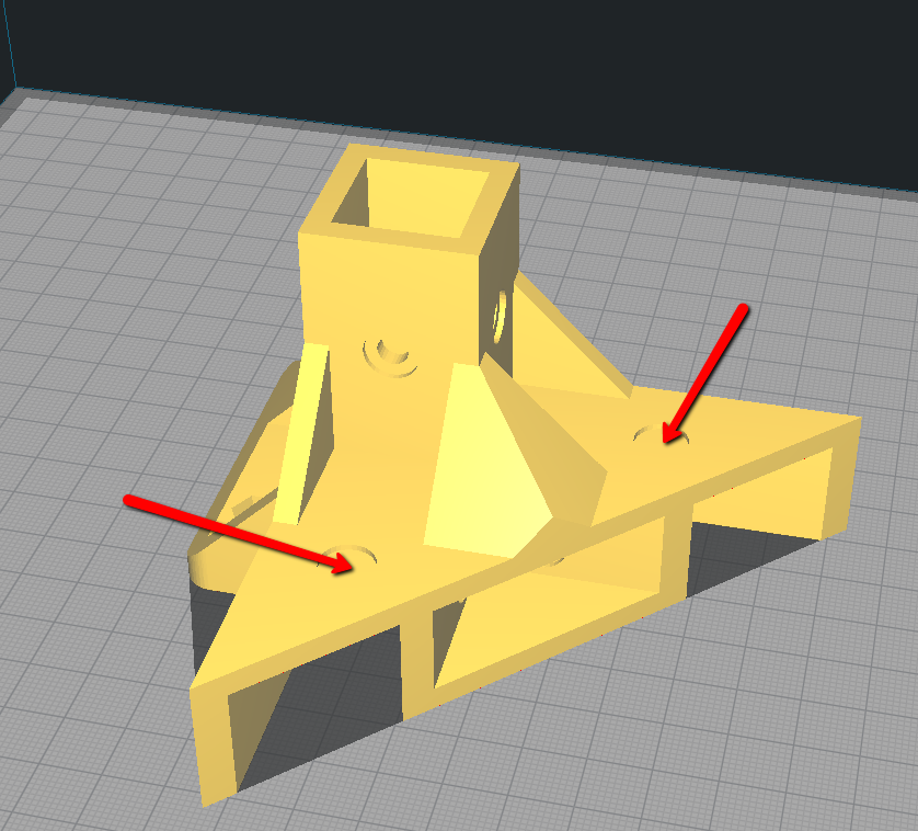
Proper Orientation for the rear brackets
One thing to be noted here is the sacrificial layers. You can see here that where the arrows point they are solid instead of holes. This is by design the layers are very thin and in most cases print in just 1 pass of your printer. You can then easily push a screw through the thin layer. Why? Because the countersink would not be possible without them. This also allows you to print these again without supports. This part will easily bridge that gap where the extrusion fits in. These don't require supports to print. Just make sure your part cooling is working properly and you'll be surprised how easily this prints.
¶ PRINT FAILURES / PARTS KNOCKED OFF BED
The above part has been tricky for a number of users because they have reported the part is knocked off the bed by the print head. This is caused by an unlevel bed 99% of the time. If your bed is level the gap will be bridged and it wont knock off the part. While your printer may be "Printing" level through software bed leveling you may still run into this issue if your bed is not level. I suggest leveling the bed the best you can and also try rotating the part. Sometimes rotating it 90° on the build plate will allow your printer to bridge the gap without failure. Printing speed can also affect this so look to slow down if you're having issues with this part in particular.
¶ SUMMARY
These parts were designed to be easy print. If you're having trouble printing them chances are its the printer or a tuning issue.