¶ Dual Z Axis on LayerFused X Series Printer
Below are the necessary parts and settings for the Marlin Firmware to implement Dual Z axis on your LayerFused X - Series 3D printer
A probe is required for this to work properly. If you have not set up a BLTouch or other type of probe please do that before you attempt this.
¶ Additional Hardware
- TMC Stepper driver (TMC2225,TMC2208,TMC2209)
- An open stepper port on your main board. (SKR 1.4 Turbo would use the E1 port)
You can choose another type of stepper driver here if you like. If you are currently using TMC2209 on your Z axis then you can use the same. It is also okay to mix the drivers as well. I have found no documentation showing that having mixed drivers on Z has caused issues given they are TMC drivers.
¶ Firmware Configuration
¶ Configuration.h
 Stepper Drivers

 #define X_DRIVER_TYPE  YOUR_DRIVER_TYPE
 #define Y_DRIVER_TYPE  YOUR_DRIVER_TYPE
 #define Z_DRIVER_TYPE  YOUR_DRIVER_TYPE
 #define Z2_DRIVER_TYPE  YOUR_DRIVER_TYPE
 #define E0_DRIVER_TYPE  YOUR_DRIVER_TYPE
¶ Configuration_adv.h
Define the number of Z steppers here.
// For Z set the number of stepper drivers
 //
 #define NUM_Z_STEPPER_DRIVERS 2   // (1-4) Z options change based on how many
To better understand how to set this up for your use, the stepper driver location on the SKR labeled Z is going to be Z1. The additional stepper that you are adding is going to be Z2. Keep this in mind when selecting your orientation for the align points.
Enable Z Stepper Auto Align
* Z Steppers Auto-Alignment
* Add the G34 command to align multiple Z steppers using a bed probe.
*/
#define Z_STEPPER_AUTO_ALIGN
#if ENABLED(Z_STEPPER_AUTO_ALIGN)
 // Define probe X and Y positions for Z1, Z2 [, Z3 [, Z4]]
 // If not defined, probe limits will be used.
 // Override with 'M422 S<index> X<pos> Y<pos>
 // #define Z_STEPPER_ALIGN_XY { {  23, 175 }, { 300,  175 } } // Only Use If Defining points Manually
 /**
  * Orientation for the automatically-calculated probe positions.
  * Override Z stepper align points with 'M422 S<index> X<pos> Y<pos>'
  *
  * 2 Steppers:  (0)     (1)
  *               |       |   2   |
  *               | 1   2 |       |
  *               |       |   1   |
  *
  * 3 Steppers:  (0)     (1)     (2)     (3)
  *               |   3   | 1     | 2   1 |     2 |
  *               |       |     3 |       | 3     |
  *               | 1   2 | 2     |   3   |     1 |
  *
  * 4 Steppers:  (0)     (1)     (2)     (3)
  *               | 4   3 | 1   4 | 2   1 | 3   2 |
  *               |       |       |       |       |
  *               | 1   2 | 2   3 | 3   4 | 4   1 |
  */
#ifndef Z_STEPPER_ALIGN_XY
   #define Z_STEPPERS_ORIENTATION 0
 #endif
To use the Auto Orientation and have it function properly, the Z motor on the right side when facing the printer needs to be connected to E1 and the Z motor on the left needs to be connected to Z.
Just to go into a little bit of detail on this, the auto-calculated probe positions will use the probe limits that have been set already by the firmware. This takes a little bit of the guess work out of it. If you would rather define the probe points yourself use #define Z_STEPPER_ALIGN_XY to define the probe points that should be used. These points are the locations of the Lead Screws.
Configure G34 Command
// On a 300mm bed a 5% grade would give a misalignment of ~1.5cm
  #define G34_MAX_GRADE              5    // (%) Maximum incline that G34 will handle
  #define Z_STEPPER_ALIGN_ITERATIONS 10    // Number of iterations to apply during alignment
  #define Z_STEPPER_ALIGN_ACC        0.01 // Stop iterating early if the accuracy is better than this
  #define RESTORE_LEVELING_AFTER_G34      // Restore leveling after G34 is done?
  // After G34, re-home Z (G28 Z) or just calculate it from the last probe heights?
  // Re-homing might be more precise in reproducing the actual 'G28 Z' homing height, especially on an uneven bed.
  #define HOME_AFTER_G34
#endif
Final configuration necessary is under the tmc_smart Section. You will notice here that a second Z stepper has been defined. Match the settings you have on the current Z Axis TMC Driver. Should look similar to this:
   #if AXIS_IS_TMC(Z)
     #define Z_CURRENT       800
     #define Z_CURRENT_HOME  Z_CURRENT
     #define Z_MICROSTEPS     16
     #define Z_RSENSE          0.11
     #define Z_CHAIN_POS      -1
     //#define Z_INTERPOLATE  true
   #endif

   #if AXIS_IS_TMC(Z2)
     #define Z2_CURRENT      800
     #define Z2_CURRENT_HOME Z2_CURRENT
     #define Z2_MICROSTEPS    16
     #define Z2_RSENSE         0.11
     #define Z2_CHAIN_POS     -1
     //#define Z2_INTERPOLATE true
   #endif
¶ Hardware Configuration
¶ E1 Stepper Driver Install
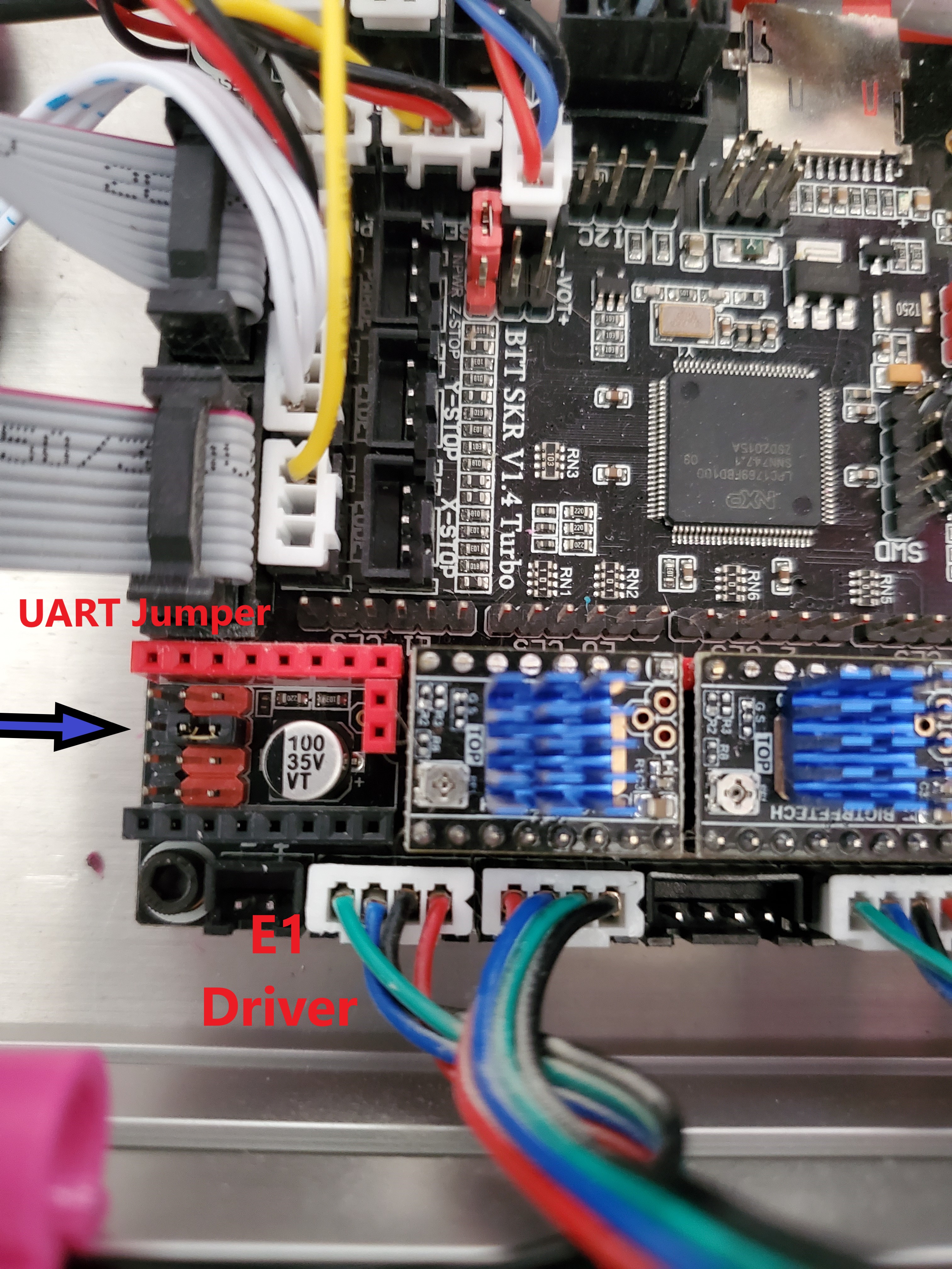
First you are going to want to ensure that you place a jumper on the UART pins for the E1 driver port on your SKR 1.4 Turbo. This should match the configuration that you have for your other stepper drivers as well.

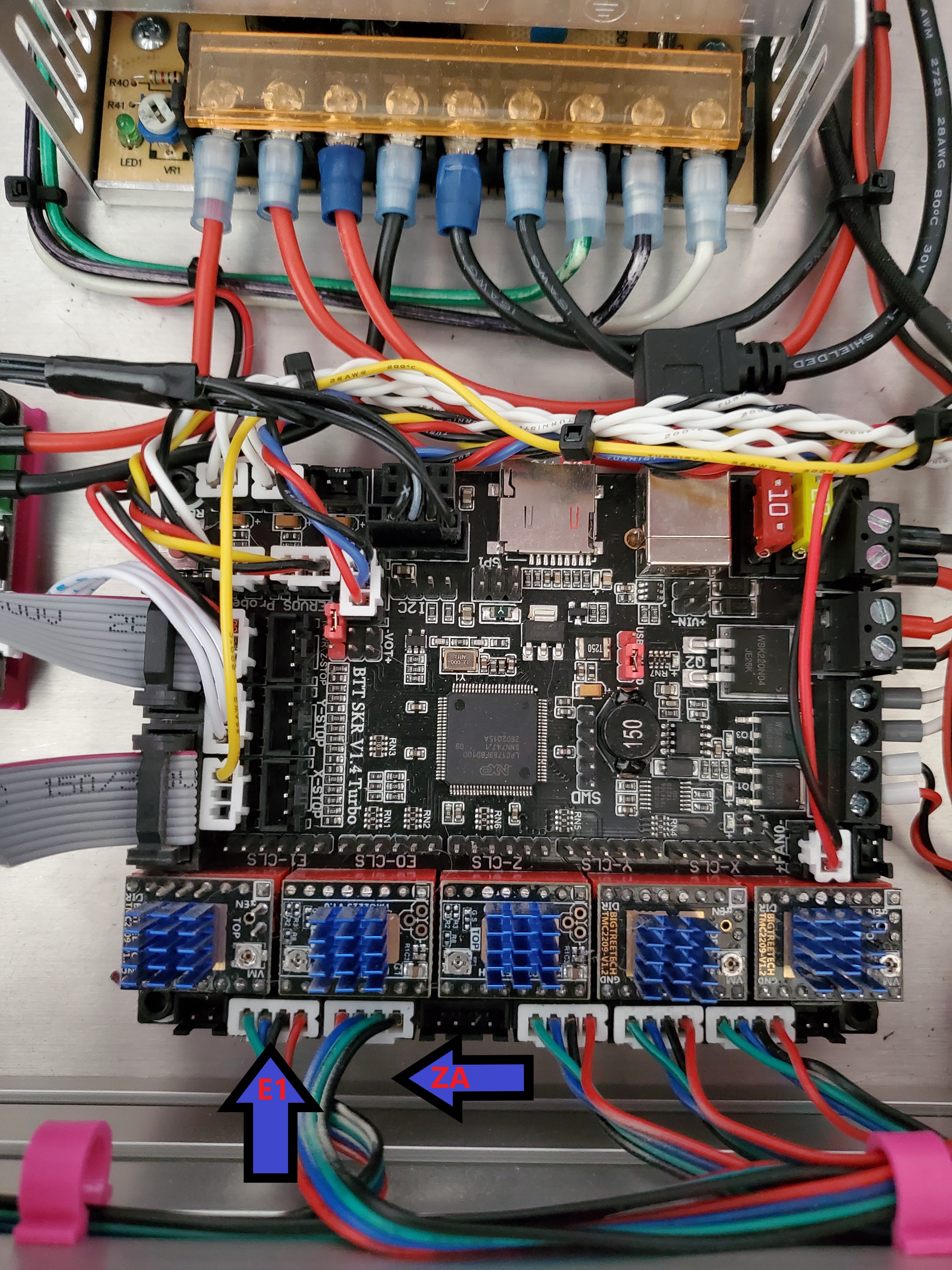
Install your Stepper Driver in the E1 Stepper slot on the board. Should look similar to the image below. All driver slots should be filled now.

This image is showing the movement of the stepper cable from the stepper cable from the ZA position over to the E1 position. In this instance The left stepper is Stepper Number 2 and the Right Stepper Number 1. On this particular board setup you would define the probe points for the G34 command. If you do not want to define the probe points then you need to reverse this connection. For more information on this and an explanation on which stepper is which see the info block under Configuration_advanced.h section.
¶ Re-Flash
Reflash your Firmware and Test everything out and make sure everything moves correctly before attempting to perform the G34 command.