¶ Overview
The lighted bed kit requires some light soldering to complete the project kit. You will need a basic pen style soldering iron and some solder to complete this task. You may find some sticky tack also helpful to hold some components while you solder. Be careful not to place the sticky tack near the solder points. You will see in these photos where we used it to hold the componets in place to solder. If you have any questions related to this please feel free to reach out to [email protected] for technical assistance with your purchase.
- Purchase at the LayerFused Shop
¶ Resistor and Capcitor Assembly
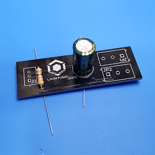
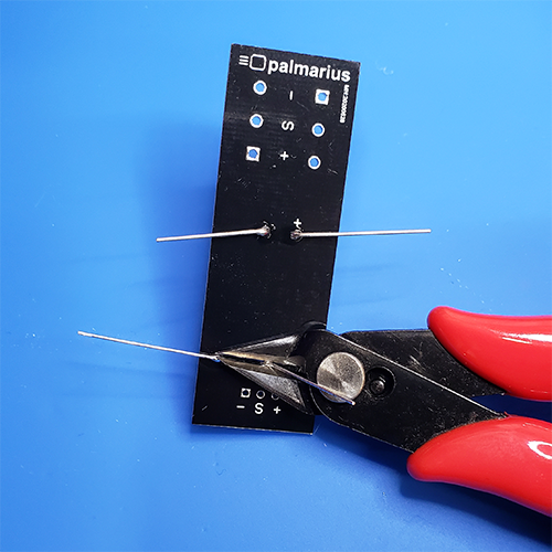
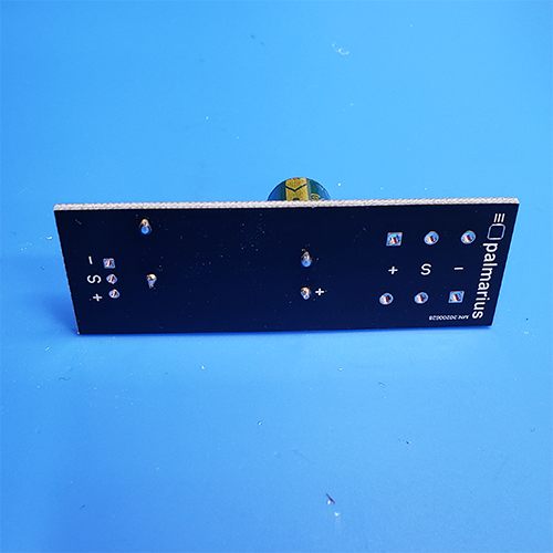
To install the resistor and capacitor you simply need to insert them through the solder holes and solder them from the other side. You can refer to the pictures below for assistance. Simply bending the leads over will hold them in place while you solder. Once you have completed soldering you simply will clip the excess leads.
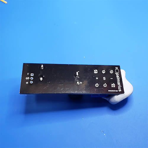
** WARNING: ** You must install the capacitor correctly as it is polarized (having a + and - side) to it. The negative lead (-) should be pointing towards the bottom of the layerfused text. The back of the circut board is also marked with the (+) solder hole so you can align it properly. Failure to install this correctly can lead to a damaged or exploding capacitor.
¶ Header Assembly
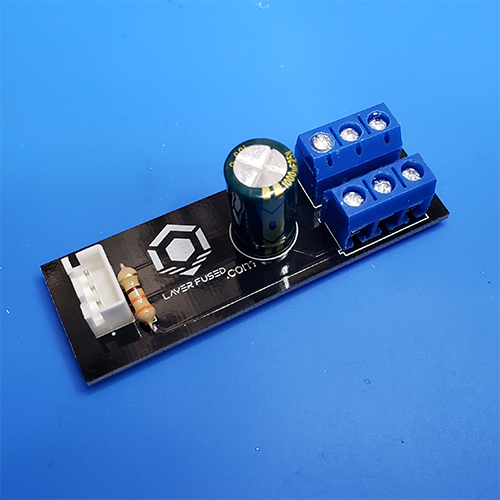
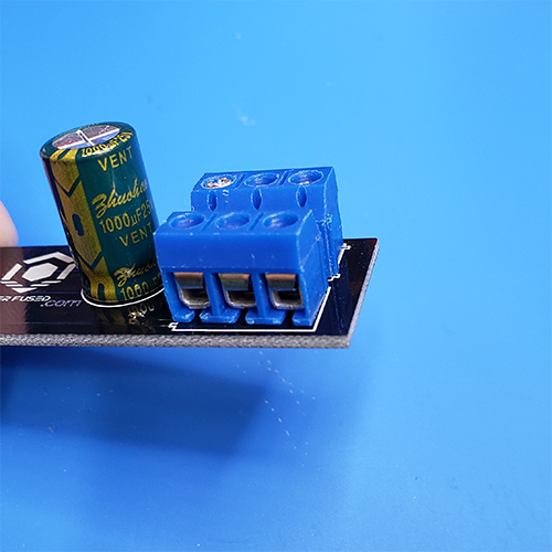
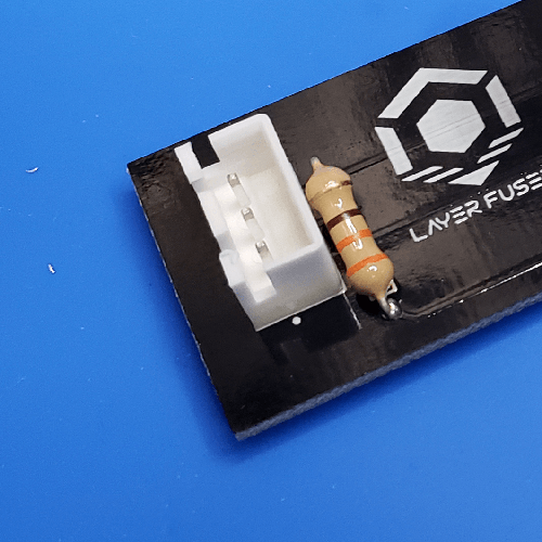
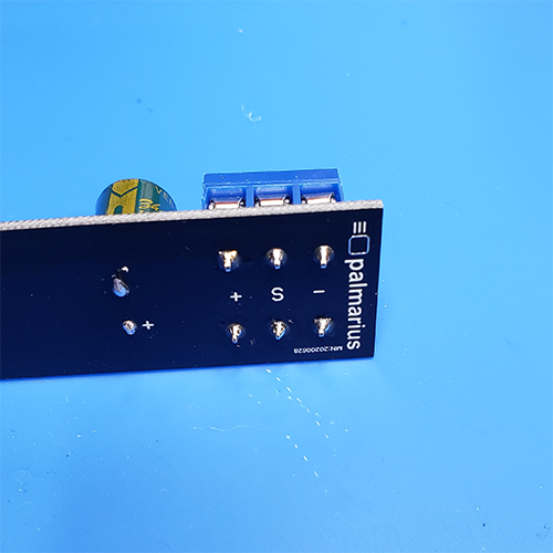
To assemble the headers you will insert them into the PCB and solder them from the other side. Please note the orientation of the screw terminal headers and the white JST header connectors. The screw terminals face outwards so you can insert a wire into them. The JST connector is mounted with the grooves in the connector facing away from the PCB. Using some sticky tack here will help you assemble this part of the project. Be sure to keep the sticky tack away from the soldering points where heat may melt it. Use the pictures below as reference.
¶ LED Assembly
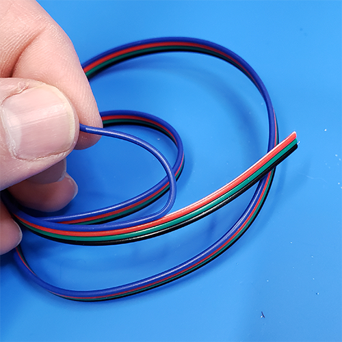
The final piece of the lighted bed kit assembly is to wire the provided wire to the LED strips. Be careful in noting the orientation of the strips. The arrow on each strip should be pointing away from the side you are soldering. Refer to the photos below as examples. Using helping hands will make it easier to hold the pieces while you solder. Remember do not connect ferrule connectors (not included) to the end of your wires until they have been installed onto the bed. If your Lighted bed kit has a 4 wire lenth, simply remove the extra lead and discard as show in the pictures below.
![]()
![]()
¶ JST Connector wiring
The JST connector included is used as a lead for you to wire to your SKR or other Mainboard. You will need your own wiring to connect this to the SKR and is not included in the kit since each printer installation varies. Be sure to properly wire the GND, Signal and 5V power correctly to the SKR or other mainboard. Reversing voltages and signals can damage your mainboard, your lighed bed kit or both.
¶ Mounting
The PCB Version of the lighted bed kit requires a different mount than the video series. Download this STL file and print it on its end. The UP should be facing up when printing and also when you install it. Make sure you install the PCB before attaching to the 3D Printer.
Lighted bed kit pcb mount.stl